 Granbo Sonic










Do Ultrasonic Cleaners Work on Carburetors?
Browse Volume:18 Classify:Support
Carburetors develop internal contamination that severely impacts engine performance. Fuel varnish, oxidized deposits, dirt particles, and corrosion products accumulate in passages measuring less than one millimeter in diameter. These obstructions disrupt precise fuel metering, causing rough idling, poor acceleration, difficult starting, and excessive fuel consumption.
Traditional cleaning methods struggle to reach internal passages without causing damage. Spray cleaners contact only external surfaces. Wire probes risk enlarging calibrated orifices. Complete disassembly for manual cleaning requires extensive mechanical knowledge and time investment.
Ultrasonic cleaning technology offers a solution that addresses carburetor contamination comprehensively. The method uses high-frequency sound waves to generate microscopic cleaning bubbles that penetrate every internal passage simultaneously. Understanding how this technology applies to carburetor restoration, what results to expect, and how to implement proper procedures helps mechanics and enthusiasts make informed decisions about cleaning equipment investments.
How Ultrasonic Cleaning Technology Functions
The Principle Behind Ultrasonic Cleaning
Cavitation Mechanics and Cleaning Action
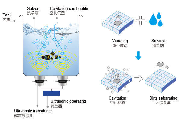
Ultrasonic cleaners generate sound waves at frequencies between 20,000 and 80,000 cycles per second. A transducer bonded to the tank bottom converts electrical signals into mechanical vibrations that propagate through the cleaning liquid. These vibrations create pressure variations throughout the fluid volume.
During low-pressure phases, microscopic bubbles form in the liquid. These cavitation bubbles grow over successive pressure cycles until reaching unstable dimensions. When high-pressure waves collapse the bubbles, they implode with tremendous localized force. Each bubble collapse generates a microjet of liquid traveling at velocities exceeding 100 meters per second.
The impact removes contamination through several mechanisms. Physical force dislodges particles adhered to surfaces. Localized temperature spikes during bubble collapse reach thousands of degrees Celsius for microseconds, breaking down organic deposits. The rapid pressure changes create fluid circulation that flushes loosened debris from confined spaces.
For carburetors, this cleaning action proves particularly valuable. The intricate internal geometry creates hundreds of surfaces that manual methods cannot reach. Cavitation bubbles form inside tiny passages, venturi throats, and metering chambers. The cleaning intensity inside a 0.5mm jet orifice equals the intensity on external surfaces.
The omnidirectional nature of ultrasonic cleaning eliminates the need to orient parts for targeted cleaning. Regardless of how a carburetor sits in the tank, all internal and external surfaces experience equivalent cleaning action. This characteristic saves time and ensures comprehensive contamination removal.
Frequency Parameters for Mechanical Parts
Operating frequency determines cavitation bubble size and collapse intensity. Lower frequencies around 25-40 kHz produce larger bubbles that implode more violently. This aggressive cleaning action suits robust mechanical components with heavy contamination.
Carburetors fall into the category where lower frequencies provide optimal results. The metal construction tolerates aggressive cavitation without damage. Heavy fuel varnish and carbon deposits require substantial energy to break down and remove. Frequencies between 28-35 kHz offer the best balance of cleaning power and component safety.
Higher frequencies above 50 kHz generate smaller, gentler bubbles appropriate for delicate items like electronics or fine jewelry. These frequencies lack sufficient energy to remove heavy carburetor deposits efficiently. Units operating above 50 kHz take longer to achieve equivalent cleaning results compared to lower frequency alternatives.
Some industrial ultrasonic cleaners offer variable frequency operation. Sweep frequency modes vary the operating frequency slightly during cleaning cycles. This prevents standing wave patterns that create dead zones where cavitation does not occur. Carburetors cleaned with sweep frequency systems show more uniform deposit removal across all surfaces.
Dual-frequency units provide both aggressive and gentle cleaning modes. The lower frequency setting addresses heavy carburetor contamination. Higher frequency modes suit cleaning precision parts, optical components, or circuit boards. This versatility justifies higher equipment costs for shops performing diverse cleaning tasks.

Do Ultrasonic Cleaners Effectively Clean Carburetors?
Why Ultrasonic Cleaning Excels at Carburetor Restoration
Ultrasonic cleaning delivers exceptional results for carburetor restoration when proper procedures are followed. The technology addresses fundamental challenges that limit traditional cleaning method effectiveness.
Carburetor internal passages range from 0.3mm to 5mm in diameter depending on circuit function. Main jets, idle jets, air bleeds, and emulsion tubes all contain precisely calibrated orifices. Manual cleaning tools cannot enter these passages without risking permanent damage to metering accuracy. Ultrasonic cleaning reaches these areas through cavitation bubble penetration rather than physical tool insertion.
Fuel varnish represents the most common carburetor contamination. Modern gasoline contains ethanol and oxidation-prone components that polymerize during storage. The resulting varnish adheres tenaciously to metal surfaces and hardens inside passages. Chemical dissolution alone requires hours or days of soaking. Ultrasonic cavitation accelerates breakdown by continuously disrupting the varnish surface and enhancing cleaning solution contact.
Testing data demonstrates ultrasonic cleaning effectiveness. Carburetors with passages 90% blocked by varnish show complete restoration of flow capacity after 20-30 minutes of ultrasonic treatment. Airflow bench measurements confirm that properly cleaned jets flow within 2-3% of original specifications. Visual inspection reveals varnish removal from internal galleries visible only through disassembled components.
The cleaning process restores function without altering calibration. Unlike abrasive methods or aggressive reaming, ultrasonic cleaning removes only contamination. The metal surfaces underneath remain unchanged. Carburetor specifications are maintained while performance is restored to factory standards.
Types of Deposits Removed from Carburetor Components
Fuel varnish and gum deposits form the primary contamination layer in carburetors exposed to stale gasoline. The amber to dark brown coating appears sticky when fresh but hardens to a shellac-like finish over time. Varnish obstructs passages, causes needles and seats to leak, and prevents smooth operation of mechanical linkages.
Ultrasonic cleaning combined with appropriate solvents dissolves varnish deposits completely. The cavitation disrupts the hardened surface while cleaning solution chemistry breaks down the polymer structure. Even varnish that resisted months of solvent soaking yields to ultrasonic treatment within 30 minutes.
Carbon deposits accumulate in carburetors from combustion blowback through intake valves. The black, sooty material contains unburned fuel residues and combustion byproducts. Carbon appears primarily around throttle shafts, venturi areas, and mixture screw passages. The deposits create rough surfaces that disrupt airflow patterns and fuel atomization.
Alkaline cleaning solutions excel at carbon removal. The combination of chemical action and ultrasonic agitation lifts carbon deposits from textured aluminum surfaces. Brightwork and polished areas emerge from cleaning without the staining that carbon deposits cause.
Corrosion products develop from moisture exposure and dissimilar metal galvanic reactions. White or green powdery deposits indicate aluminum oxide or copper carbonate formation. Corrosion roughens surfaces, narrows passages, and creates pitting that affects sealing surfaces.
Mildly acidic cleaning solutions dissolve metal oxide and carbonate deposits. The ultrasonic action flushes dissolved corrosion products from pitted areas and crevices. Subsequent passivation treatments prevent rapid re-corrosion after cleaning.
Dirt and sediment enter carburetors through worn air filters or compromised fuel systems. Silica particles, rust from fuel tanks, and organic debris accumulate in float bowls and plug small passages. The abrasive nature of dirt particles accelerates wear on needle valves and throttle shafts.
Physical agitation from cavitation dislodges embedded dirt particles. The cleaning solution suspends removed contamination, preventing redeposition. Filtration or solution changes between cleaning cycles remove accumulated debris.
Oil and grease contamination occurs from crankcase breather systems and improper storage. Petroleum residues coat surfaces and mix with other contaminants to form sludge. The sticky deposits trap dirt and promote varnish formation.
Degreasing solutions emulsify oil and grease, allowing ultrasonic action to flush the contamination completely. Even passages filled with sludge drain clear after proper ultrasonic treatment.
Carburetor Design Characteristics and Cleaning Challenges
Carburetor
Internal Passage Complexity and Contamination Points
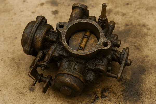
Carburetors contain dozens of interconnected passages that distribute fuel and air to various engine operating conditions. Understanding this internal architecture clarifies why ultrasonic cleaning proves so effective compared to external cleaning methods.
The main fuel passage delivers gasoline from the float bowl to the venturi area. This passage measures 3-6mm in diameter and typically includes bends, restrictions, and connection points for secondary circuits. Varnish coating the passage walls reduces effective diameter and restricts fuel flow. Manual access requires complete disassembly and passage drilling, risking damage to precision surfaces.
Idle and low-speed circuits branch from the main system through passages as small as 0.8mm. These circuits control fuel delivery at closed throttle and partial throttle positions. The narrow passages plug easily from varnish or debris. Symptoms include rough idle, stalling when decelerating, and off-idle hesitation. Ultrasonic cleaning restores idle circuit function by penetrating the narrow passages that cleaning sprays cannot reach.
High-speed air bleeds introduce controlled air into fuel streams for proper mixture ratios. These passages range from 0.5mm to 2mm diameter and often include multiple bends. Partially blocked air bleeds cause rich running conditions at high throttle openings. The resulting black exhaust smoke, fouled spark plugs, and poor fuel economy indicate air bleed contamination. Ultrasonic treatment clears these passages without requiring precise reaming that risks over-sizing.
Accelerator pump circuits include check valves, discharge nozzles, and connecting passages. Contamination in this system causes stumbling or hesitation during rapid throttle opening. The check valves particularly require clean seating surfaces to function properly. Ultrasonic cleaning removes deposits from valve seats and discharge nozzles without disassembling delicate pump mechanisms.
Jet Orifices and Precision Metering Systems
Carburetor jets contain calibrated orifices that meter precise fuel quantities. Main jets, idle jets, power jets, and air correction jets all use hole sizes specified to within 0.02mm tolerances. Even minor contamination dramatically affects metering accuracy.
A main jet with a nominal 1.20mm diameter that accumulates 0.10mm of varnish coating experiences approximately 15% flow reduction. This translates to noticeably lean running, hesitation under load, and potential engine damage from excess temperatures. Traditional cleaning attempts using wire risk enlarging the orifice by removing brass material along with contamination.
Ultrasonic cleaning restores jet flow without dimensional changes. The cavitation removes only the contamination layer, leaving precision brass surfaces intact. Flow testing before and after ultrasonic cleaning confirms that jet specifications remain within factory tolerances.
Emulsion tubes contain arrays of small holes that create fuel/air mixing before delivery to the engine. These tubes feature 10-30 holes ranging from 0.5mm to 1.5mm diameter in precise patterns. Contamination of even a few holes disrupts the designed mixture pattern. Complete cleaning requires removing deposits from all holes simultaneously, which only ultrasonic treatment accomplishes practically.
Float Bowls and Sediment Accumulation Zones
Float bowls serve as fuel reservoirs at the bottom of carburetors. Gravity causes dirt, rust, and water to settle in the bowl. The accumulated sediment creates multiple problems. Particles drawn into fuel passages cause blockages downstream. Water promotes corrosion and supports microbial growth. Varnish formation accelerates in contaminated fuel.
The bowl corners and recesses trap sediment that simple draining does not remove. Ultrasonic cleaning agitates the entire bowl volume, suspending contamination for removal. The cleaning solution flushes deposits from stamped recesses and threaded drain plug areas that brushing cannot reach.
Float pivot points and needle valve seats require particular cleanliness. Debris on these surfaces prevents proper fuel level control. Resulting symptoms include flooding, fuel starvation, or erratic fuel delivery. Ultrasonic cleaning removes contamination from these precision surfaces without the abrasive wear that manual scrubbing causes.
Material Compatibility Considerations
Aluminum Alloy Bodies and Casting Surfaces
Most carburetor bodies use aluminum casting alloys for their combination of light weight, corrosion resistance, and manufacturing economy. These alloys tolerate ultrasonic cleaning well when appropriate solutions and parameters are selected.
Alkaline cleaning solutions at pH 10-12 provide effective degreasing and carbon removal for aluminum. The metal shows excellent resistance to mild alkalis. However, strongly alkaline solutions above pH 13 attack aluminum, causing surface etching and darkening. Maintaining proper solution chemistry prevents damage while achieving thorough cleaning.
Aluminum oxide forms naturally on aluminum surfaces, creating a protective barrier. Aggressive cleaning solutions or excessive treatment duration can remove this oxide layer, leaving surfaces vulnerable to rapid corrosion. Proper ultrasonic parameters maintain the protective oxide while removing contamination.
Cast aluminum surfaces feature rough textures from the casting process. These textured areas trap contamination more readily than smooth surfaces. Ultrasonic cleaning proves particularly valuable for cast aluminum because cavitation reaches into surface irregularities. The result shows consistent cleaning across both smooth and textured areas.
Some carburetors feature anodized aluminum components for enhanced corrosion resistance and appearance. The anodizing process creates a thicker oxide layer with improved durability. Standard ultrasonic cleaning does not damage properly applied anodizing. However, damaged anodizing that shows wear or peeling may continue degrading during ultrasonic treatment.
Brass Jets and Metering Components
Brass alloys are used extensively for jets, needle valves, seats, and precision metering parts. The material offers excellent machinability for producing accurate dimensions and good corrosion resistance in fuel environments.
Brass components tolerate ultrasonic cleaning exceptionally well. The material resists cavitation erosion even during extended cleaning cycles. Chemical compatibility spans a wide range of cleaning solutions from acidic to alkaline formulations.
Concern sometimes arises about dezincification, where zinc leaches from brass alloys in corrosive environments. Standard ultrasonic cleaning durations at normal temperatures do not cause measurable dezincification. The cleaning cycle ends long before significant material degradation occurs.
Soft solder joints occasionally appear in carburetor construction, particularly in vintage or artisan-built units. Solder shows lower melting temperatures than base metals. Cleaning solution temperatures should remain below 80 degrees Celsius to prevent softening solder joints. Most carburetor cleaning occurs at 50-65 degrees Celsius, providing adequate safety margin.
Rubber Gaskets and Seal Preservation
Carburetors contain rubber or synthetic elastomer components including accelerator pump diaphragms, inlet needle tips, primer bulbs, and various seals. These components require different handling than metal parts during ultrasonic cleaning.
Most elastomers degrade when exposed to aggressive solvents and elevated temperatures. Removal of all rubber and elastomeric components before ultrasonic cleaning represents the standard recommendation. This practice prevents premature seal deterioration and ensures compatibility with stronger cleaning solutions.
Nitrile rubber (Buna-N) shows the best solvent resistance among common carburetor seal materials. Short exposure to petroleum solvents during ultrasonic cleaning causes minimal swelling or degradation. However, extended soaking, particularly at elevated temperatures, accelerates aging. Manufacturers typically recommend replacing all seals and gaskets during carburetor rebuilding regardless of cleaning method.
Viton fluoroelastomer seals demonstrate exceptional chemical resistance. These premium seals tolerate most cleaning solutions without damage. Some modern carburetors incorporate Viton components specifically to allow thorough chemical cleaning during service. Verification of seal material composition allows informed decisions about removal necessity.
Cork gaskets absorb cleaning solutions and swell significantly. The dimensional changes prevent proper sealing after reinstallation. Cork gaskets must be removed before ultrasonic cleaning and replaced with new parts during reassembly.
Zinc Die-Cast Parts and Corrosion Concerns
Some carburetor components, particularly housings and covers on small engines, use zinc die-casting (pot metal). This material offers manufacturing economy but presents special considerations for ultrasonic cleaning.
Zinc alloys are susceptible to corrosion in alkaline environments. Strongly alkaline cleaning solutions attack zinc, producing white corrosion products and surface pitting. pH-neutral or mildly acidic cleaning solutions prevent this damage while still providing effective cleaning.
Older zinc die-cast parts may suffer from internal corrosion and material degradation even before cleaning. The aggressive agitation from ultrasonic treatment can reveal pre-existing weakness by causing fragile castings to crack. This outcome, while unfortunate, actually prevents failure during engine operation where consequences would be worse.
Modern zinc die-cast carburetor components often receive protective plating or coating. Chrome plating, nickel plating, or paint barriers protect the underlying zinc. Intact coatings allow normal ultrasonic cleaning. Damaged coatings that expose base metal require careful solution selection to prevent accelerated corrosion.
Proper Disassembly Requirements Before Cleaning
Components That Must Be Removed
Effective ultrasonic carburetor cleaning requires complete disassembly into individual metal components. The process exposes all surfaces to cleaning action and protects incompatible materials from damage.
All rubber and elastomer parts must be removed. This includes O-rings, gaskets, diaphragms, inlet needle tips, primer bulbs, and any soft seals. These components degrade in cleaning solutions and should be replaced during reassembly regardless of apparent condition.
Throttle and choke shaft assemblies sometimes contain pressed-in bearings or seals at the shaft ends. These assemblies require careful evaluation. Removal of external seals prevents damage, but pressed bearings may be serviceable without disassembly if the carburetor is oriented to minimize direct cavitation on bearing surfaces.
Float assemblies warrant special attention. Traditional cork floats must be removed, as they absorb cleaning solution and become waterlogged. Modern hollow brass or plastic floats can remain attached to the pivot mechanism if free from damage. Inspection for punctures or leaks prevents cleaning solution from entering hollow floats.
Electrical components including idle stop solenoids, mixture control solenoids, and sensors must be removed. Ultrasonic cleaning damages electronic circuits and motor windings. External cleaning of electrical components uses different methods appropriate for electronic devices.
Welsh plugs and pressed-in cups seal internal passages in some carburetors. These components typically remain in place during cleaning. The plugs prevent passage access during service, and ultrasonic cleaning reaches around them through connected pathways. Removal risks damaging sealing surfaces unless replacement is planned.
Documenting Assembly Configuration
Carburetor disassembly produces dozens of small parts with specific installation positions. Documentation prevents assembly errors that compromise function.
Digital photography provides the most practical documentation method. Photographs taken at each disassembly stage show part positions, orientation, and relationships. Wide shots establish overall configuration while close-ups capture small details like spring hook positions and lever alignments.
Parts organization during disassembly prevents mixing components from different circuits. Magnetic parts trays, divided containers, or egg cartons separate jets, screws, and small parts. Labeling containers with circuit names or locations facilitates correct reassembly.
Adjustable components including mixture screws and idle speed screws should have initial positions recorded. Counting turns from fully seated to original position provides baseline settings. Adjustment knobs, if removed, require documentation of index positions relative to carburetor bodies.
Linkage geometry, particularly on multi-barrel carburetors, involves complex relationships between throttle plates, choke plates, and accelerator pumps. Sketches or annotated photographs capture linkage positions that must be replicated during reassembly. Incorrect linkage timing causes drivability issues difficult to diagnose.
Protecting Non-Cleanable Parts
Some carburetor assemblies incorporate components unsuitable for ultrasonic cleaning that cannot easily be removed. Protecting these parts during cleaning prevents damage while allowing thorough treatment of carburetor bodies.
Throttle shaft bushings pressed into carburetor bodies may contain lubricating materials that dissolve in cleaning solvents. Removal and replacement requires special tools and precision work. Moderate ultrasonic exposure with petroleum-based cleaners causes minimal bushing degradation. Limiting cleaning cycles to 15-20 minutes and avoiding strongly alkaline solutions protects bushings adequately.
Decorative chrome plating or painted surfaces may show cosmetic importance beyond function. While ultrasonic cleaning does not typically damage sound plating, weakened chrome may lift or blister. Testing a small inconspicuous area before full cleaning identifies potential problems. Alternatively, masking sensitive areas with acid-resistant tape provides protection.
Serial number stampings and identification markings sometimes use filled engraving where paint occupies stamped depressions. Aggressive ultrasonic cleaning removes this paint fill. Photography preserves the information, or masking protects original markings for originality-focused restorations.
Selecting Appropriate Cleaning Solutions for Carburetors
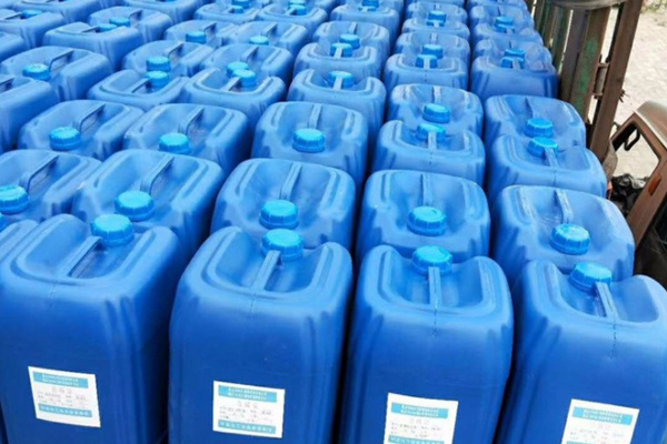
Ultrasonic Cleaning Agent
Alkaline Degreasers and Heavy Deposit Removal
Alkaline cleaning solutions excel at removing carbon deposits, oxidized oils, and heavy grease contamination from carburetor exteriors. These formulations typically contain sodium hydroxide, sodium metasilicate, or other alkaline compounds at pH levels between 10 and 13.
The alkaline chemistry saponifies oils and fats, converting them to water-soluble soaps. This action dissolves grease and facilitates removal through ultrasonic agitation. Carbon deposits soften under alkaline attack, allowing cavitation to dislodge particles.
Concentration control affects cleaning speed and material safety. Heavy-duty alkaline cleaners at full concentration provide maximum cleaning power for extremely contaminated carburetors. Dilution to 50-75% of recommended concentration offers gentler action suitable for routine cleaning with less aluminum etching risk.
Temperature significantly influences alkaline cleaner performance. Heating solutions to 55-65 degrees Celsius accelerates chemical reactions and reduces solution viscosity. The improved cleaning speed allows shorter cycle times. However, temperatures exceeding 70 degrees Celsius increase aluminum attack rates and may damage remaining elastomer components.
Aluminum-safe alkaline formulations incorporate inhibitors that slow metal attack while maintaining cleaning effectiveness. These specialized products cost more than industrial alkaline cleaners but provide better material compatibility. Carburetor cleaning applications justify the incremental cost through reduced risk of part damage.
Petroleum-Based Solvents vs. Water-Based Formulations
Petroleum solvents including mineral spirits, kerosene, and specialty hydrocarbon blends dissolve fuel varnish through chemical similarity. The principle that “like dissolves like” makes petroleum solvents effective for fuel system contamination.
Ultrasonic cleaning with petroleum solvents requires proper equipment and safety measures. The solvents produce flammable vapors that create explosion risks if ignited. Only ultrasonic cleaners rated for flammable solvent use should be employed. These units incorporate sealed heating elements, spark-suppressing switches, and vapor ventilation.
Petroleum solvents show excellent material compatibility. Aluminum, brass, steel, and other carburetor metals tolerate extended exposure without corrosion. Some elastomers swell in petroleum products, reinforcing the need to remove rubber components before cleaning.
Water-based formulations offer safety advantages over petroleum solvents. Non-flammable aqueous solutions eliminate explosion risks and simplify equipment requirements. Standard ultrasonic cleaners with conventional heating elements safely accommodate water-based chemistries.
Surfactant-enhanced water-based cleaners provide effective fuel varnish removal despite lacking solvent action. The surfactants reduce surface tension, allowing water penetration into contamination layers. Emulsifying agents suspend dissolved varnish in solution, preventing redeposition. Chelating compounds sequester metal ions that contribute to deposit formation.
Effectiveness comparison between petroleum and water-based solutions depends on contamination types. Heavy grease and oil respond better to petroleum solvents. Hardened varnish and carbon deposits clean more effectively with alkaline water-based formulations. Many professional shops maintain both solution types for addressing different cleaning challenges.
Commercial Carburetor Cleaning Chemicals
Specialized carburetor cleaning chemicals designed for ultrasonic use optimize formulation for this specific application. These products balance cleaning effectiveness, material safety, and user convenience.
Leading formulations combine several active ingredients for broad-spectrum cleaning. Alkaline builders provide carbon removal and degreasing. Surfactants enhance wetting and penetration. Corrosion inhibitors protect aluminum and zinc. Chelating agents prevent mineral precipitation in hard water areas.
Concentrated liquid products require dilution before use. Typical dilution ratios range from 10:1 to 20:1, allowing users to adjust cleaning strength based on contamination levels. This flexibility accommodates light maintenance cleaning and heavy restoration work with a single product.
Powdered formulations offer economic advantages through reduced shipping costs and convenient storage. The powder dissolves completely in warm water to produce working solutions. Shelf life extends years when kept dry, versus months for liquid products that may separate or degrade.
Pre-mixed ready-to-use solutions eliminate dilution steps and ensure consistent concentration. The convenience benefits users performing occasional carburetor cleaning who prefer not maintaining concentrated stocks. The higher per-use cost reflects convenience rather than enhanced performance.
Biodegradable formulations address environmental concerns and disposal requirements. These products use plant-derived surfactants and avoid heavy metals or persistent organic compounds. Spent cleaning solution disposal follows local wastewater regulations, often allowing drain disposal after pH neutralization.
Solution Temperature Optimization
Temperature profoundly affects ultrasonic cleaning effectiveness. Heat energy accelerates chemical reactions, reduces cleaning solution viscosity, and enhances cavitation intensity.
Room temperature cleaning at 20-25 degrees Celsius provides baseline results suitable for lightly contaminated carburetors. The gentle conditions minimize material stress and energy consumption. Cleaning cycles extend to 30-45 minutes to achieve thorough contamination removal.
Elevated temperatures between 50-65 degrees Celsius deliver optimal carburetor cleaning performance. Chemical activity increases substantially within this range. Varnish softens, allowing easier disruption by cavitation. Solution viscosity decreases, improving bubble formation and collapse characteristics. Typical cleaning times reduce to 15-25 minutes with equivalent or superior results compared to room temperature treatment.
Excessive temperatures above 75 degrees Celsius create problems despite faster chemical action. Aluminum surfaces may show increased etching and darkening. Remaining elastomers deteriorate rapidly. Cleaning solution evaporation accelerates, requiring frequent replenishment. Most importantly, cavitation intensity actually decreases at extreme temperatures due to increased vapor pressure reducing bubble collapse violence.
Optimal temperature varies slightly with cleaning solution chemistry. Alkaline solutions show peak performance around 60-65 degrees Celsius. Petroleum-based solvents clean effectively at lower temperatures around 40-50 degrees Celsius due to flash point considerations. Manufacturer recommendations specific to each product provide authoritative guidance.
Temperature monitoring ensures consistent results between cleaning sessions. Digital displays on advanced ultrasonic cleaners show real-time solution temperature. External thermometers verify temperature in units lacking built-in sensing. Allowing heated solutions to stabilize at target temperature before starting cleaning cycles ensures consistent treatment conditions.
Operating Parameters for Carburetor Cleaning
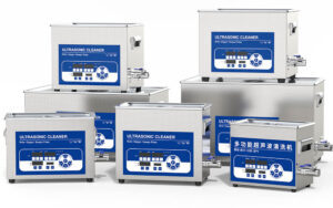
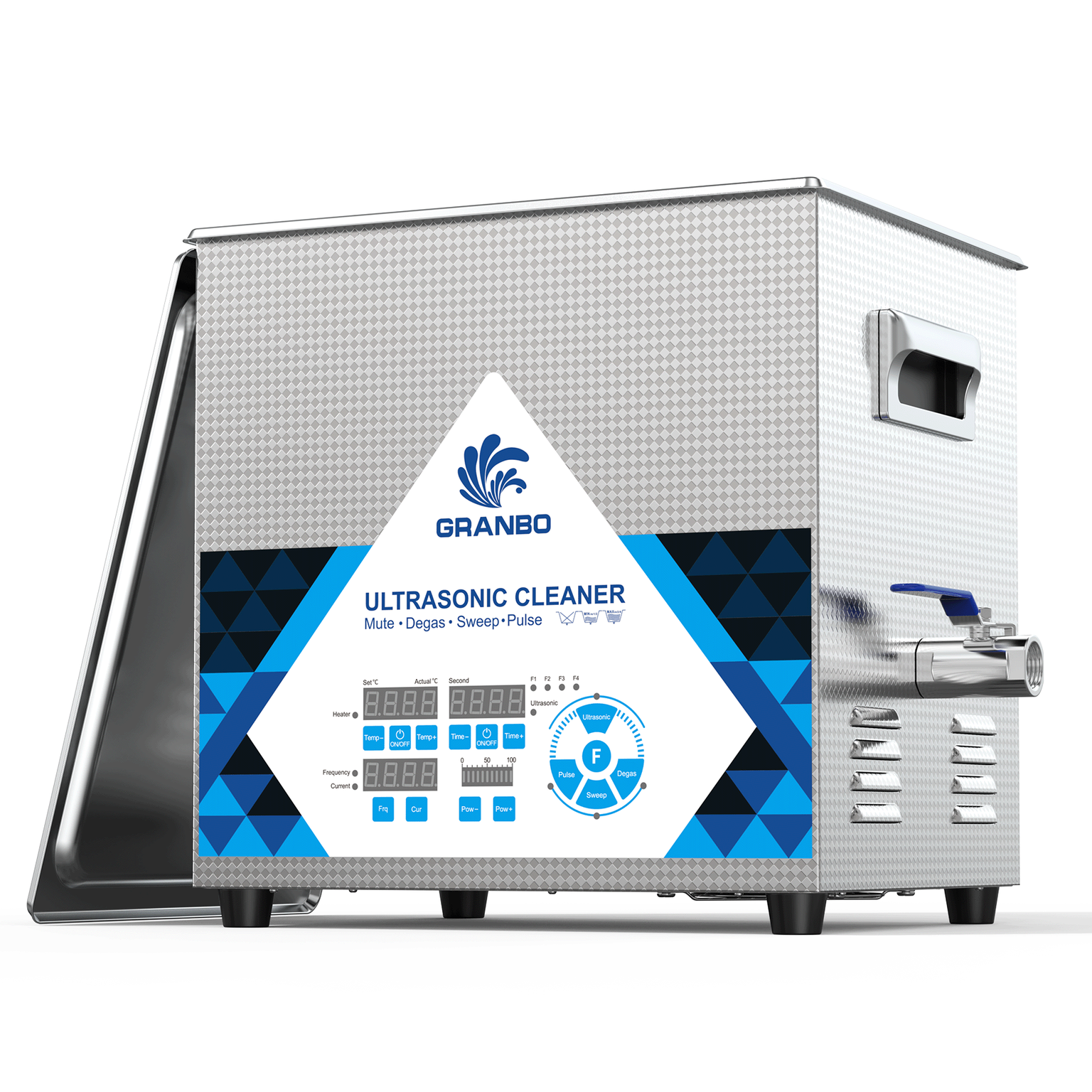
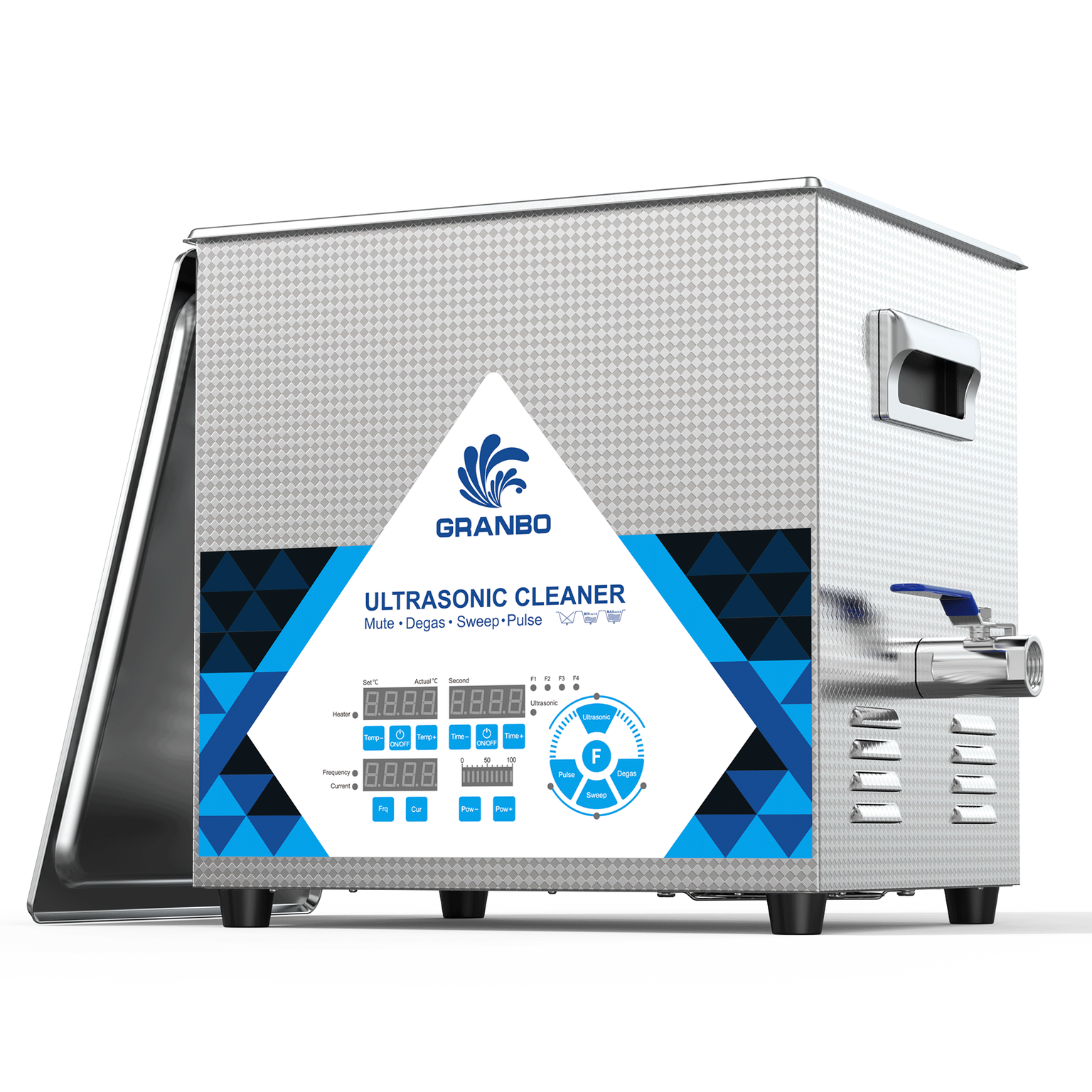
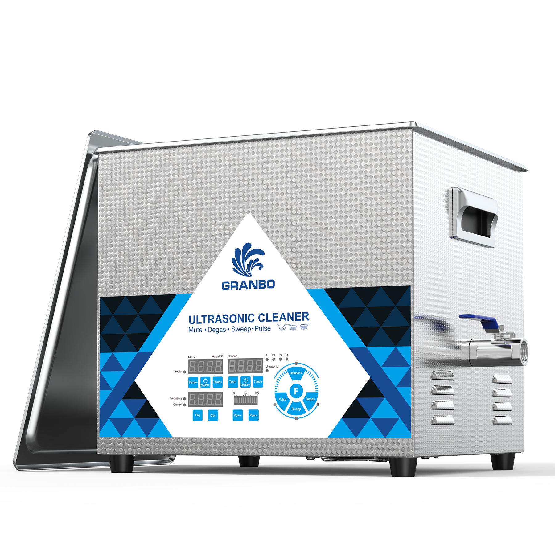
Granbo GL Series Ultrasonic Cleaner
Optimal Frequency Settings for Metal Parts
Carburetor cleaning benefits from lower ultrasonic frequencies that generate aggressive cavitation suitable for robust metal components. The 25-40 kHz range provides ideal characteristics for this application.
Units operating at 28-35 kHz represent the sweet spot for carburetor work. The cavitation intensity efficiently disrupts hardened varnish and carbon deposits. Cleaning times remain reasonable at 15-30 minutes for most contamination levels. The frequency is low enough for powerful cleaning yet high enough to avoid excessive noise generation.
Lower frequencies around 25 kHz create even more violent cavitation with enhanced cleaning power. This aggressive action suits extremely contaminated carburetors from long-term storage or severe neglect. However, the lower frequency generates more audible noise and may cause lightweight parts to vibrate against tank walls.
Higher frequencies above 45 kHz produce gentler cleaning appropriate for delicate items but lack the power necessary for efficient carburetor cleaning. Units operating at these frequencies require extended cycle times, sometimes doubling the duration needed at 28-35 kHz. The gentler action may leave stubborn deposits in narrow passages.
Professional carburetor rebuilding shops often select dual-frequency ultrasonic cleaners offering both 28 kHz and 40 kHz operation. The lower frequency handles heavy contamination during initial cleaning. Switching to 40 kHz for a final cleaning cycle provides thorough treatment of precision components like jets and needle valves without aggressive material stress.
Cleaning Cycle Duration and Effectiveness
Proper cycle duration balances thorough contamination removal against efficiency and material preservation. Insufficient cleaning time leaves deposits in narrow passages, while excessive duration wastes time without improving results.
Lightly contaminated carburetors from recent service or preventive maintenance require 10-15 minutes of ultrasonic cleaning. This duration removes fresh varnish formation, light carbon deposits, and surface contamination. Visual inspection after initial cleaning determines if extended treatment is necessary.
Moderately contaminated carburetors showing visible varnish buildup and some passage restriction benefit from 20-30 minute cleaning cycles. The extended duration allows cleaning solution to penetrate hardened deposits while cavitation progressively disrupts contamination layers. Most carburetors fall into this category and achieve satisfactory results within this timeframe.
Heavily contaminated carburetors from multi-year storage or severe neglect may require multiple cleaning cycles totaling 45-60 minutes. Breaking total treatment into 20-minute sessions separated by solution changes prevents deposit recontamination. Fresh cleaning solution for each cycle maintains chemical activity and removes suspended debris.
Diminishing returns occur beyond 60 minutes total ultrasonic exposure. Deposits resistant to this extended treatment typically involve chemical bonding or physical changes that ultrasonic cleaning cannot address. Additional treatment wastes time and energy while potentially stressing metal surfaces through prolonged cavitation exposure.
Progress monitoring during extended cleaning optimizes cycle duration. Periodic inspection at 15-20 minute intervals shows remaining contamination location and severity. Cleaning continues until visual inspection confirms passage cleanliness and no further improvement occurs between inspection intervals.
Temperature Control and Heat Management
Maintaining optimal solution temperature throughout cleaning cycles requires active management. Ultrasonic transducer inefficiency and cavitation energy conversion generate heat that continuously raises solution temperature.
Units with integrated heating elements and thermostatic control simplify temperature management. Setting the target temperature to 60 degrees Celsius maintains conditions within optimal range automatically. The thermostat cycles heating on and off to compensate for heat loss through the tank walls while preventing excessive temperature rise.
Manual temperature control requires vigilance with basic ultrasonic cleaners lacking thermostatic features. Starting with pre-heated solution at target temperature provides ideal initial conditions. Monitoring temperature every 10 minutes detects excessive rise requiring intervention. Adding small amounts of cool water or allowing brief cooling periods maintains temperature within acceptable range.
Insulated tank construction reduces heat loss and improves temperature stability. Stainless steel tanks with double-wall construction or external insulation maintain temperature more consistently than single-wall designs. The improved thermal performance benefits cleaning consistency and reduces energy consumption.
Ambient temperature affects heat management requirements. Summer operation in hot shops causes solution temperatures to climb rapidly. Winter operation in cold environments requires more heating energy to reach target temperature. Climate control in the work area moderates these seasonal variations.
Multiple Cycle Strategies for Stubborn Deposits
Sequential cleaning cycles using different solution chemistries maximize contamination removal from severely fouled carburetors. This staged approach addresses various deposit types sequentially rather than expecting a single solution to handle all contamination.
Initial cycles using alkaline degreasers remove heavy grease, oil, and carbon deposits. The strong cleaning action strips away surface contamination layers, exposing hardened varnish underneath. A 20-minute cycle with fresh alkaline solution at 60 degrees Celsius provides aggressive initial treatment.
Intermediate cycles transition to specialized carburetor cleaning solutions targeting fuel varnish. The moderate alkalinity and surfactant content dissolve polymerized fuel deposits softened during initial alkaline treatment. A 15-20 minute cycle removes the bulk of remaining varnish.
Final cycles with fresh cleaning solution provide polishing action and verification of passage cleanliness. A 10-minute final cycle flushes loosened debris and reveals any remaining problem areas requiring attention. The clean solution prevents redeposition of contamination removed during earlier cycles.
Rinse cycles between chemical changes prevent contamination carryover and chemical interactions. A 5-minute ultrasonic rinse in plain water or mineral spirits removes residual cleaning solution. Allowing parts to drain between cycles reduces chemical mixing in subsequent baths.
Comparing Ultrasonic Cleaning to Traditional Methods
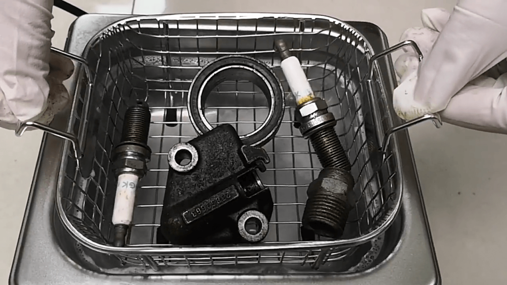
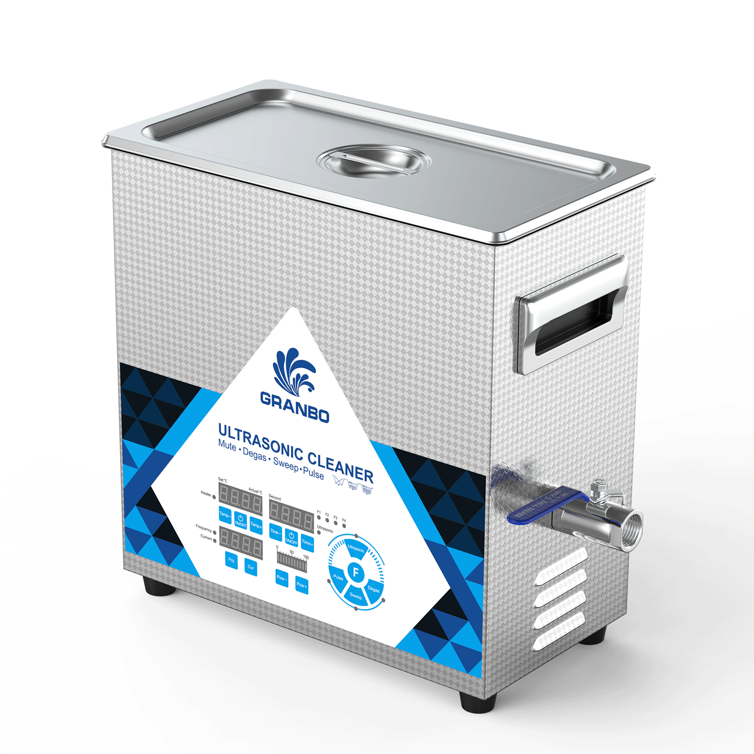
1 to 3.2L Machine Clean Carburetor And Hardware
Aerosol Spray Cleaners and Surface Limitations
Carburetor spray cleaners packaged in aerosol cans represent the most accessible cleaning method. These products contain strong solvents under pressure that flush external surfaces and accessible passages. The convenience and low cost make spray cleaners popular for quick service.
However, spray cleaners contact only surfaces directly exposed to spray application. Internal passages beyond the spray stream remain contaminated. Complex carburetor geometry creates dead zones where spray penetration does not occur. The result shows partially cleaned exteriors with untouched internal contamination.
Spray cleaning requires carburetor disassembly to access internal passages. Even with disassembly, blind passages and narrow circuits resist spray cleaning. Jets and air bleeds smaller than 1mm diameter fill with solvent through capillary action but lack mechanical agitation to dislodge hardened deposits.
Solvent evaporation from spray cleaners occurs rapidly after application. The brief contact time limits chemical action on resistant deposits. Multiple applications address this limitation but increase solvent consumption and cost. Compared to ultrasonic cleaning, equivalent results require significantly more time, solvent, and effort.
Environmental and health considerations favor ultrasonic cleaning over spray methods. Aerosol solvents disperse into workspace air, creating inhalation exposure and air quality concerns. Proper ventilation becomes critical but adds cost and complexity. Ultrasonic cleaning contains solutions within tanks, minimizing atmospheric release.
Solvent Soaking and Time Requirements
Immersion soaking in solvent-filled containers provides better penetration than spray application. Carburetors submerge completely, allowing solvent access to all external surfaces and passage entrances. The extended contact time promotes chemical dissolution of deposits.
Traditional soaking requires 24-72 hours for significant varnish removal from internal passages. The passive chemical action slowly softens deposits without mechanical assistance. Patience becomes essential, particularly for heavily contaminated units. Rush situations or production environments cannot accommodate multi-day cleaning durations.
Soaking solutions become contaminated with dissolved deposits and suspended particles. The dirty solvent progressively loses cleaning effectiveness as contamination accumulates. Periodic solution changes maintain chemical activity but increase solvent consumption and disposal costs.
Brush agitation during soaking improves results but remains limited to accessible surfaces. Internal passages still rely on passive soaking alone. The combination of overnight soaking plus morning brush scrubbing represents common practice but still leaves internal contamination.
Ultrasonic cleaning compresses the timeline dramatically. Results equivalent to 48 hours of passive soaking occur in 20-30 minutes with ultrasonic agitation. The time savings translate directly to productivity improvements in professional shops and convenience for home mechanics.
Manual Wire Brushing and Jet Reaming
Wire brushes, toothbrushes, and brass bristle brushes provide mechanical contamination removal for external surfaces and large passages. The scrubbing action physically dislodges deposits that chemical treatment softens. Visible improvement provides satisfaction and confirms cleaning progress.
However, brushing damages soft metals and precision surfaces. Steel bristles scratch aluminum, removing material along with contamination. Even brass bristles cause wear on soft brass jets with repeated scrubbing. The dimensional changes may affect calibration tolerances.
Jet reaming using precision wire attempts to clear blocked orifices. This practice carries significant risk despite sometimes being necessary as a last resort. Wire diameter matching the jet opening displaces contamination but may also enlarge the orifice. Oversized jets lean fuel delivery, potentially causing engine damage.
Proper jet reaming requires taper pin reamers specifically sized for each jet specification. The tools cut precise dimensions while clearing blockages. However, availability and cost of proper reaming tools limit accessibility. Improvised methods using drill bits or arbitrary wire sizes nearly always damage jets beyond specification.
Ultrasonic cleaning eliminates the need for risky reaming procedures. The cavitation clears blocked jets without physical tool insertion. Original dimensional tolerances remain intact while flow capacity restores to specification. The non-contact cleaning preserves precision parts that wire methods damage.
Professional Carburetor Rebuild Services
Professional carburetor rebuilding services offer complete restoration including ultrasonic cleaning, new parts installation, calibration verification, and functional testing. Experienced technicians handle disassembly, cleaning, reassembly, and adjustment with specialized knowledge and equipment.
Service costs typically range from $150 to $400 per carburetor depending on complexity and parts requirements. The investment makes sense for rare, complex, or high-value applications where correct restoration ensures optimal performance. Vintage vehicles, aircraft engines, and marine applications often justify professional service.
Turnaround time for professional service ranges from several days to weeks depending on shop workload and parts availability. Rush service may be available at premium cost. The time requirement proves inconvenient when immediate results are needed.
Investing in ultrasonic cleaning equipment allows equivalent or superior results at substantially lower cost per cleaning. The equipment purchase cost amortizes over multiple carburetor cleanings. DIY cleaning provides schedule control, immediate availability, and learning opportunities about carburetor function.
Post-Cleaning Procedures and Verification
Compressed Air Drying Techniques
Thorough drying prevents water spots, corrosion formation, and cleaning solution residue from contaminating reassembled carburetors. Compressed air provides efficient moisture removal from internal passages and external surfaces.
Air pressure requirements range from 30-90 PSI for effective drying. Higher pressures provide faster drying but risk damaging delicate components. Pressure regulation protects parts while ensuring adequate flow through narrow passages.
Systematic air application starting at passage entrances forces liquid through connected circuits. Blowing through main jets forces solution from fuel bowls through metering passages. Air directed into air bleeds clears these circuits completely. The methodical approach ensures no trapped liquid remains in internal galleries.
Warm air accelerates drying through enhanced evaporation. Heat guns set to low temperature, approximately 50-70 degrees Celsius, quickly evaporate moisture from metal surfaces. Excessive heat risks damaging remaining elastomers or assembled components, making temperature control important.
Visual inspection during drying confirms complete solution removal. Visible wetness indicates areas requiring additional air application. Inverted positioning drains liquid from recessed areas where pooling occurs. Complete drying prevents water contamination mixing with fuel during subsequent operation.
Passage Inspection and Flow Testing
Visual inspection through passages using strong lighting verifies contamination removal. Flashlights, inspection lamps, or fiber optic sources illuminate passage interiors. Clean passages show bright metal surfaces without dark deposits or discoloration.
Magnification assists inspection of small jets and air bleeds. Jeweler’s loupes providing 5-10X magnification reveal remaining deposits invisible to unaided vision. Magnified inspection sets higher cleanliness standards ensuring optimal function.
Flow testing using compressed air or carburetor cleaner spray confirms passage patency. Air blown through jets at moderate pressure should flow freely without restriction. Comparison between similar jets on multi-barrel carburetors identifies cleaning effectiveness differences.
Calibrated orifice gauges measure jet opening diameters precisely. These tools confirm that cleaning has not enlarged critical metering orifices beyond specification. Measurements within 0.02mm of nominal specifications indicate proper cleaning without dimensional damage.
Light transmission testing passes bright light through jets and passages. An observer positioned opposite the light source looks for transmitted light indicating clear passage. Blocked or partially obstructed circuits appear dark despite external illumination.
Reassembly Practices with New Gaskets
Carburetor reassembly following ultrasonic cleaning requires new gaskets and seals regardless of old component appearance. Cleaning solutions degrade elastomers even when removed before ultrasonic treatment through residual contamination and prior aging.
Gasket kits specific to carburetor model numbers ensure correct parts. These kits include all necessary gaskets, O-rings, seals, and often needle valves and seats. The comprehensive replacement guarantees leak-free operation and optimal performance.
Proper gasket installation techniques prevent vacuum leaks and fuel leakage. Gaskets seat against clean, dry surfaces without adhesives in most applications. Thin, uniform torque on fasteners compresses gaskets evenly without over-compression that causes extrusion or splitting.
Fuel-resistant sealants apply to specific locations including welsh plug perimeters, bowl gaskets on rough cast surfaces, and threaded fittings. Non-hardening sealants allow future disassembly without damaged components. Avoid excessive sealant application that squeezes into passages and creates contamination.
Float level adjustment restores factory specifications for proper fuel delivery. Following manufacturer procedures ensures correct fuel height relative to jets and metering systems. Incorrect float levels cause rich or lean running regardless of cleanliness.
Limitations and Problem Scenarios
When Ultrasonic Cleaning Cannot Restore Function
Ultrasonic cleaning removes contamination but cannot repair damage or restore worn components. Understanding these limitations prevents unrealistic expectations and wasted effort on carburetors requiring replacement rather than cleaning.
Severely corroded aluminum bodies showing pitting, erosion, or crystalline deposits may clean cosmetically but retain surface damage. The roughened surfaces promote rapid recontamination and may affect sealing surfaces. Replacement becomes necessary when corrosion compromises structural integrity or sealing capability.
Worn throttle shaft bores cause vacuum leaks that cleaning cannot address. The enlarged bores allow air infiltration around shafts during operation, leaning the mixture and causing rough running. Repair requires bushing installation or carburetor replacement depending on available repair options.
Damaged threads on adjustment screws, jets, or mounting points prevent proper assembly or adjustment. Cleaning does not restore thread integrity. Thread repair options include helicoil insertion, oversize taps, or epoxy thread restoration depending on specific damage and loads involved.
Stripped or damaged screw heads from previous service attempts may defy removal even after ultrasonic cleaning. The cleaning exposes damaged heads more clearly but does not facilitate extraction. Specialized extraction tools or destructive removal techniques become necessary.
Damaged Components Requiring Replacement
Physical damage including cracks, breaks, and deformation requires component replacement. Ultrasonic cleaning reveals damage by removing obscuring contamination but cannot repair structural failures.
Cracked carburetor bodies leak fuel externally or create internal vacuum leaks between circuits. Hairline cracks invisible before cleaning become apparent once deposits are removed. Attempting repair with epoxies or sealants rarely succeeds in fuel-wetted applications due to poor adhesion and chemical attack.
Broken mounting tabs, linkage connections, or adjustment mechanisms prevent proper carburetor installation or operation. The mechanical damage requires welding repairs, brazing, or replacement depending on material and stress levels. Cleaning simply reveals the need for these corrective measures.
Collapsed or deformed internal passages from corrosion or overtightening restrict flow despite being clean. The dimensional changes affect carburetor calibration unpredictably. Flow testing before and after cleaning identifies these problems requiring component replacement.
Worn needle valve seats allow excessive fuel delivery and flooding. The soft seat material erodes from debris impact and chemical attack over time. Ultrasonic cleaning removes contamination but does not restore sealing surface integrity. Replacement seats and needles represent standard rebuild practice.
Varnish Types That Resist Ultrasonic Treatment
Certain varnish formations show exceptional resistance to ultrasonic cleaning through chemical composition or bonding characteristics. These deposits may require alternative treatment approaches.
Shellac-hard varnish from extensive heat exposure creates crosslinked polymer structures resisting typical cleaning solutions. The varnish adheres with exceptional tenacity to metal surfaces. Extended ultrasonic treatment with aggressive alkaline solutions eventually removes these deposits, but cycle times may extend to 60+ minutes.
Varnish contaminated with metallic particles from engine wear creates abrasive deposits harder than pure fuel varnish. The embedded metal particles resist chemical dissolution and mechanical disruption. Sequential treatment with acidic solutions to dissolve metal followed by alkaline cleaning for varnish proves more effective than either chemistry alone.
Deposits in inaccessible internal galleries without fluid circulation may persist despite ultrasonic cleaning. While cavitation theoretically reaches all liquid-filled spaces, practical limitations including trapped air or contamination blocking passage entrances prevent complete cleaning. Disassembly exposing all passages to direct solution contact resolves this limitation.